Finite element modeling of frequency-analog sensors
HSG-IMIT
Institute for Micro- and Information Technology of the Hahn-Schickard-Gesellschaft
for Applied Research e.V.,
Villingen-Schwenningen
2.1 Introduction
2.1.1 Functional principle of resonant sensors
The principle of a resonant sensor is based on the dependence of the natural frequency of the resonator on an external physical variable (e.g. pressure, force, temperature) by affecting the state of stress or changing the inertia of the resonator via a mass loading. The resonance frequency represents a quasi-digital output signal as a measured variable. The sensor is characterized on the one hand by its passive resonator properties such as natural frequency, vibration mode and the coupling to the measured quantity, and on the other hand by the properties of the vibration excitation and detection, for example the mode selectivity, the efficiency of the energy coupling and the resolution of the detection system.
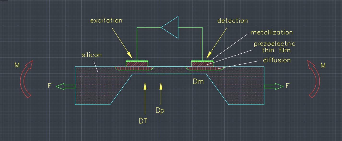
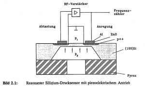
In the following, the frequency-analog functional principle will be illustrated using the example of a resonant, micro-mechanical pressure sensor, which is shown schematically in Figure 2.1. The excitation is achieved by a piezo-electric thin film (here: zinc oxide) which, with the transverse piezo-electric effect, generates bending moments on the membrane surface as a result of expansions and contractions when an alternating electrical voltage is applied, thus leading to periodic membrane deflections. The silicon resonator is deformed as a result of a pressure difference between the top and bottom of the diaphragm. The amount of static deflection is many times greater than the dynamic oscillation amplitude. If the static deflection is sufficiently large, membrane stresses are created by reaction forces, which lead to a stiffening of the resonator so that the resonant frequency changes in accordance with the measured quantity. Conversely, if the piezo-electric effect is also used for vibration detection, the sensor can be operated in natural resonance with a suitable evaluation circuit and the frequency change can be read out via a frequency counter.
Figure 2.1: Resonant silicon pressure sensor with piezoelectric actuator
2.1.2 Material properties of micromechanical materials
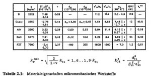
Table 2.1 summarizes the mechanical, thermal, piezoelectric and dielectric material properties of some important materials used in micromechanics. In addition to monocrystalline silicon, monocrystalline quartz is also used as a substrate material for resonant sensors. Since silicon is not piezo-electric, aluminum nitride (AlN) and zinc oxide (ZnO) are used as piezo-electric active transducer layers. Compared to the polycrystalline materials AlN and ZnO produced using thin-film technology (sputtering process), PZT piezoceramics (lead zirconate titanate) are characterized by extremely high piezoelectric coupling coefficients d_ij, while single-crystal quartz is characterized by relatively low piezoelectric coupling coefficients d_ij. The electro-mechanical coupling factor is a measure of the efficiency of the conversion of electrical energy into mechanical energy. The effective coupling factor k_eff is made up of a material-dependent and a geometry-dependent component and can only be determined with the coupled FE calculations for a given resonator geometry.
The material-dependent transverse and planar coupling factors k_31 and k_pmat for pure transverse and planar transducers depend on the mechanical stiffness coefficient S_11E, the Poisson’s ratio v (= – S_12/S_11), and the piezoelectric and di-electric constants d_31 and e_33T of the piezoelectric thin film (for relationships see Table 2.1) [VIB 81]. Since the material parameters of micro-engineered layer systems are strongly influenced by the technological manufacturing process, they may differ considerably from those of the solid-state material (bulk) and generally exhibit process-related internal stresses. The material data given refer only for aluminum nitride to layers a few micrometers thick [Fra 88], the other data refer to bulk material [LB 82], [Tic 80], [VIB 81].
Table 2.1: Material properties of micromechanical materials
2.1.3 Analytical design of resonant sensors
Bending beam and membrane resonators are especially suitable for the application as resonant force and pressure sensors. Assuming ideal clamping conditions and homogeneous, isotropic material properties, the resonance frequencies and load-dependent frequency changes of the resonator can be determined analytically for simple resonator geometries. Using the analytical approaches, the operating point of resonant sensors, i.e. the fundamental resonant frequency and the measured quantity sensitivity, can be set via a suitable choice of geometric dimensions.
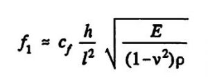
The resonant frequencies for the bending vibrations depend on the geometric dimensions, resonator length l and thickness h, the type of clamping and the material parameters, Young’s modulus E, Poisson’s ratio v and material density ρ. The following applies to the resonant frequency of the fundamental bending vibration [Alb 82]:
(Equation 1)
The proportionality constant c_f depends on the resonator geometry and the vibration mode and is approximately 1.028 for double-sided clamped flexural beams. The force sensitivity of beam resonators is discussed in Chapter 5.
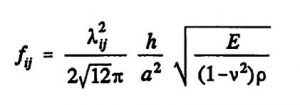
The analytical relationships given in the literature for diaphragms for the deflection and stress state, as well as the resonant frequencies, are based on Kirchhoff’s plate and shell theory and assume flat objects whose lateral dimensions are significantly greater than their thickness. Various approximation methods (e.g. [You 50]) are used to determine the natural frequencies and vibration modes. For the resonant frequencies f_ij of plane membranes, [Ble 84] applies:
(Equation 2)
where:
- E, v : isotropic modulus of elasticity, Poisson’s ratio
- a,h : membrane side length, thickness
- i,j : number of half-waves in x or y direction
- ρ : density (material homogeneity assumed)
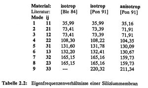
Table 2.2: Natural frequency ratios of a silicon diaphragm
For the natural frequency shift as a result of a pressure effect, a superposition of a static and dynamic problem results. In the first step, the diaphragm center deflection is determined as a function of the acting pressure; in the second step, the frequency shift is determined as a function of the diaphragm deflection. The superposition results in the frequency shift as a function of the acting pressure. Various approaches are used in the literature, in which linear correlations are given for relatively thick diaphragms at small deflections and non-linear correlations for thin diaphragms at large deflections. For quadratic, rigidly clamped plates of thickness h, the non-linear relationship between the acting pressure p and the membrane center deflection d is according to [Cha 87]:
(Equation 3)
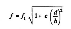
This equation can be solved using Kardan’s solution formula and used to calculate the resonance frequency change as a function of the deflection [Utt 87]:
(Equation 4)
The constant c depends on the clamping and the diaphragm shape. For the design of resonant silicon sensors that are subject to strains in the <110> crystal direction during bending vibrations, the modulus of elasticity E = 168.9 GPa and the Poisson’s ratio v = 0.063 are assumed. The density ρ of silicon is 2329 kg/m³. The material data given refer to room temperature.
2.1.4 Numerical modeling methods for resonant sensors
When designing micromechanical sensors, simulation using the finite element method (FEM) plays an important role, as it allows even complex transducer geometries with arbitrary boundary conditions and the functional principles to be realized technologically to be modeled in the design phase, taking process-technical restrictions into account. Analytical estimations, which can usually only be carried out for simple structural geometries, serve as initial values for the numeric model calculations. By varying the parameters of the FE model, the influence of the oscillator geometry and the material properties of the thin-film systems can be studied in advance. The FE method thus allows resonant, micromechanical sensors to be suitably designed and the sensor properties to be specifically optimized.
Dynamic FE calculations are used to determine the natural frequencies and vibration modes (modal analysis) of various sensor structures (single and triple beams, diaphragms) and to determine the influence of the measured variable to be investigated. The pressure or force sensitivity is calculated by a non-linear, static FE calculation in which the change in stiffness of the overall system caused by the measured quantity is determined. The changed structural stiffness is then used to determine the natural frequencies of the sensor under this load. By comparing the calculated sensor characteristics with experimental data of micro-mechanical resonator structures in multilayer structures, the internal stress of the thin films can be deduced.
Coupled FE calculations (multiphysics) taking into account the electromechanical interaction enable a precise prediction of the static and dynamic behavior of piezoelectrically driven sensors. The frequency response behavior is determined by modeling the mechanical amplitude spectrum and the electrical impedance and phase response as a function of the piezoelectric excitation. In particular, the layer thickness ratio was optimized with regard to the excitation efficiency and the electrode geometry was derived for the most selective vibration excitation possible.
This report documents the possibilities of using coupled dynamic FE calculations in the design process of resonant micromechanical sensors. A comparison of numerical and experimental results shows the achievable modeling accuracies of the FE calculation method. The commercially available finite element program system ANSYS was used for the modeling [SASI].
2.2 Dynamic properties of micromechanical resonators
Due to the different transducer geometries and the specific resonator characteristics of resonant sensors, such as material properties and boundary conditions, different vibration modes occur. While only flexural vibrations and their harmonics occur in thin silicon membranes due to the moment excitation, superimposed, complex vibration modes (e.g. thickness shear vibrations, chapter 3) are also possible in quartz membranes due to the crystal structure. In the case of beam resonators, longitudinal and torsional vibrations as well as superpositions of these vibration modes can occur with both materials in addition to the flexural vibrations.
2.2.1 Quartz double tuning forks
The calculation of the natural frequencies of quartz oscillators allows the accuracy of the FE method to be tested, as the material properties of monocrystalline quartz are known very precisely [Bri 85] and no stresses due to thin layers have to be taken into account. The flexural resonance frequencies of force sensors based on quartz double ended tuning forks (DETF) could be calculated using simple, two-dimensional FE model approaches with isotropic material behavior, so that the deviations from experimentally measured values were less than 2 %. However, the modeling of complex vibration modes requires a three-dimensional formulation including the anisotropic material behavior and the piezoelectric properties, as well as the consideration of the electrical termination conditions of the electrodes. Figure 2.2 shows the mode spectrum of an idealized quartz double tuning fork (tuning fork length: 5.0 mm, tuning fork width: 0.2 mm). A 3D model was created in order to calculate all possible vibration modes of the quartz double ended tuning fork, including torsional and superimposed modes. In the lower frequency range, different flexural vibrations (y-, z-direction) dominate, while as the frequency increases, torsional and superimposed xyz vibration states increasingly occur.
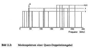 Figure 2.2: Mode spectrum of a quartz double ended tuning fork
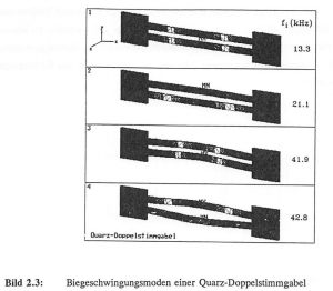
Figure 2.3 shows the vibrational modes of the quartz double ended tuning fork (DETF) corresponding to the first four natural frequencies. In the natural vibration mode, in which the double tuning fork is operated as a force sensor, the tuning fork bars vibrate in antiphase to each other so that no torques are coupled out into the mounting areas. The fourth oscillation mode has the highest oscillation quality combined with the highest force resolution due to the tuning fork oscillations in antiphase. In the higher vibration modes, symmetrical (in-phase) and anti-symmetrical (180° out-of-phase) tuning fork vibrations alternate and the number of vibration maxima increases. The double ended tuning fork is stiffer in the y-direction than in the z-direction, so that the transverse z-oscillations are lowest in frequency at 13.3 (in-phase) and 21.1 kHz (antiphase). The two transverse fundamental vibrations in the y-direction at 41.9 and 42.8 kHz are higher in frequency due to the increased bending stiffness in the y-direction.
Figure 2.3: Flexural vibration modes of a quartz double ended tuning fork
When calculating the force sensitivity of quartz double ended tuning forks, an axial tensile force is applied to the sensor and the change in resonance frequency is calculated. The force sensitivity of the quartz sensor depends on the ratio of the tuning fork length to the tuning fork width. The force sensitivities were calculated for different vibration modes. The y-A1 mode has the highest sensitivity at around 1.83 l/N, while the basic y-S1 mode is 1.64 l/N (y-S1: symmetrical mode, y-A1: antiphase mode). The force sensitivities of the higher flexural vibration modes decrease sharply. Measurements on commercially available quartz double ended tuning forks (Micro Crystal, CH-Grenchen), which are excited in the antiphase mode y-A1, resulted in a value of approximately 1.42 l/N. The force-frequency characteristics were calculated for different tuning fork widths.
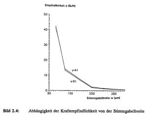
Figure 2.4 shows the force sensitivities η of the two bending vibration modes in the beam plane as a function of the tuning fork width w. The tuning fork width was varied from 0.4 to 0.08 mm and resulted in a maximum sensitivity of approximately 42 l/N for the y-A1 vibration mode. However, the non-linearity of the characteristic curve at the minimum bar width is about 2.5 % in relation to the maximum measuring range (here: 10 N).
Figure 2.4: Dependence of the force sensitivity on the tuning fork width
2.2.2 Silicon beam resonators with different cross-sections
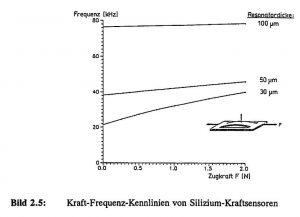
Wet-chemically etched beam resonators in (100) silicon have a prismatic cross-section. In force sensor applications, stabilizing bars (so-called shunts) are provided in wafer thickness parallel to the vibrating beam as overload protection. Figure 2.5 shows the numerically calculated force-frequency characteristics of silicon beam resonators as a function of the beam thickness for the fundamental mode.
Figure 2.5: Force-frequency characteristics of silicon force sensors
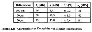
Table 2.3 summarizes the characteristic parameters, the fundamental resonance frequency f_1, the force sensitivity η, the characteristic curve non-linearity NL and the maximum tensile stress σ_x (at F = 2 N) of the calculated silicon force sensors.
Table 2.3: Characteristic parameters of silicon force sensors
The frequency shift depends on the magnitude of the mechanical stress in the resonator, so that the force sensitivity can be increased by changing the resonator cross-section. By laser structuring of silicon in combination with anisotropic wet etching technology (see also Chapter 5), triangular beam cross-sections with an acute angle of 35° can be produced in (110) silicon, which exhibit a higher resonator stress than prismatic beams at the same force application [Ala 92].
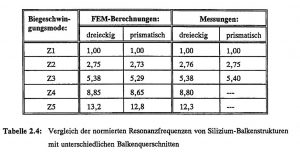
Table 2.4 lists the numerically calculated resonant frequency factors c_i = f_i / f_1 of single beam structures with different beam cross-sections made of silicon and compares them with measured values. The frequencies are normalized to the respective fundamental mode Z1. The various harmonics out of the beam plane are labeled Z2 to Z5. The beam length was 3 mm, the width 200 μm, while the thickness was around 70 μm (see also Chapter 6).
Table 2.4: Comparison of the normalized resonant frequencies of silicon beam structures with different beam cross-sections
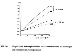
Figure 2.6 shows the normalized resonant frequencies of beam transducers with triangular and prismatic beam cross-sections as a function of the mechanical tensile stress in the bending beam. The triangular beam cross-sections achieve a force sensitivity that is about 30 % higher than the prismatic ones [Ala 92].
Figure 2.6: Comparison of the force sensitivity of beam resonators with triangular and prismatic beam cross-sections
A further aspect in the design of resonant sensor geometries is the selection of the most favorable resonator mount in order to keep the internal damping contributions of the oscillator as low as possible. Chapter 5 reports on the realization of a resonant force sensor based on a triple beam structure made of silicon. Increased vibration quality is achieved through torque compensation. In addition, suitable structuring of the resonator mounting results in mode decoupling, which is expressed by improved mode selectivity, i.e. unimodality of the resonator system.
2.2.3 Resonant silicon membrane pressure sensors
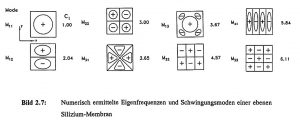
Both flat and structured diaphragms made of silicon (chapter 2.1.1) or quartz with piezoelectric excitation can be considered for resonant pressure sensor applications. In collaboration with the HSG-IMIT, the consortium partner MotoMeter GmbH has developed a resonant quartz pressure sensor based on a structured membrane, the design and realization of which is reported on in detail in Chapter 3. The consortium partner Robert Bosch GmbH has produced resonant pressure sensors in silicon, which were modelled and further optimized in close cooperation with HSG-IMIT. Various FE models have therefore been developed for modeling resonant silicon pressure sensors and the influence of the geometry and material properties under different clamping conditions has been investigated. Both two-dimensional FE models with isotropic material properties and three-dimensional FE models taking into account the full material anisotropy of the silicon with the 54.7° edge clamping due to the (111) planes were investigated. The maximum deviation of the resonant frequencies between the analytical and the numerical description is about 10 %. The difference between the isotropic and anisotropic material approach for silicon membranes leads to a deviation of about 3 % in the natural frequencies of the fundamental bending vibrations. A further reduction in the resonance frequencies occurs as a result of the reduced rigidity due to the inclined edge clamping, which is of the same order of magnitude. A detailed description of the individual model influences can be found in [Sch 92]. Figure 2.7 shows the vibration modes M_ij calculated on a 2D model and the corresponding frequency factors c_i = f_i / f_1 of a flat silicon diaphragm. The indices i, j correspond to the number of vibration maxima in the x and y directions respectively.
Figure 2.7: Numerically determined natural frequencies and vibration modes of a flat silicon diaphragm
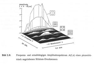
In order to experimentally characterize the piezoelectrically controlled pressure sensor membranes, they were optically characterized using a laser Doppler vibrometer (POLYTEC OFV1102). Figure 2.8 shows the frequency- and location-dependent amplitude spectrum A(f,x) of a pressure sensor manufactured by the joint venture partner Robert Bosch GmbH. The diaphragm side length was 9.2 mm, the silicon thickness 50 μm and the ZnO layer thickness around 15 μm. The resonance amplitude of the fundamental mode M_11 was around 1 μm. The vibration quality at normal air pressure was about 100 for the fundamental mode and about 310 and 360 for the modes M_13 and M_33. A comparison of the experimentally and numerically determined lateral mode characteristics along the center of the membrane shows close agreement. With sufficiently large vibration amplitudes (several hundred nm), all experimentally determined modes could be assigned with the help of the FEM results.
Figure 2.8: Frequency and position-dependent amplitude spectrum A(f,x) of a piezoelectrically driven silicon pressure sensor
The resonance behavior of pressure-loaded diaphragms is influenced by the diaphragm stresses induced in the diaphragm, which occur at “large” deflections. The non-linear effects depend on the ratio of the diaphragm thickness to the edge length, the acting pressure and the type of clamping [Fab 92a]. The relationship between the resonant frequency f_0 of an unbraced diaphragm and a planar stress σ in the diaphragm is as follows [Bou 90]:
(Equation 5)
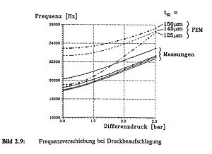
This stress can be caused by external loads, e.g. pressurization or temperature stress, or by process-related internal stresses. Figure 2.9 shows the results of various FE calculations and optical measurements of a 148 μm thick silicon membrane with an approx. 15 μm ZnO layer. Based on the resonance frequency deviation of about 4 kHz between measurement and simulation, an internal compressive stress of the ZnO layer of about σ ≈ – 100 MPa can be concluded using equation (5). The influence of the layer stress causes a considerable reduction in the resonant frequency of the unloaded diaphragm compared to the theoretical value. The measured pressure sensitivity of the sensor in the measuring range up to 3 bar is about 1 Hz/mbar. Although the correct frequency value could be reproduced by reducing the diaphragm thickness to 125 μm, this is associated with increased pressure sensitivity [Sch 92].
Figure 2.9: Frequency shift during pressurization
2.3 Piezoelectric excitation of resonant sensors
For efficient piezoelectric excitation by ZnO thin films, suitably designed electrode shapes and the optimum thickness ratio of the ZnO layer to the thickness of the silicon structure are crucial. The efficiency of the excitation can be determined by the effective electro-mechanical coupling factor k_eff. In contrast to the material-dependent component k_mat, i.e. the mechanical and electrical properties of the piezo-electric ZnO layer (Chapter 2.1.2), this depends on the layer thickness ratio, the component geometry and the boundary conditions. It is therefore the aim of the piezo-electric FE calculations to predict and optimize the sensor properties in a targeted manner, including the coupling of the mechanical variables (displacements) and the electrical variables (potential). The modeling of the piezo-electric effect, the interaction between the spatial displacements and the electric field, is carried out in ANSYS by a coupling directly on the finite element level. The implemented approach makes it possible to investigate the static and dynamic behavior of linear piezoelectric media with anisotropic material properties [AUM 92]. Micromechanical resonators can be modeled, which are excited by piezoelectric thin films. In contrast to mechanical excitation, this takes place directly through the electrical field variables, so that the mechanical structural behavior can be calculated and various electrical parameters derived, taking into account the electro-mechanical conversion.
2.3.1 Modeling the electrical sensor behaviour
The piezo-electrically excited force and pressure sensors are operated in an oscillator circuit in which the impedance and phase behavior (two-pole operation) or the electrical transmission behavior (four-pole operation) of the sensor elements must be known. The effective coupling factor can be determined by calculating the frequency-dependent impedance and phase response. For the effective coupling factor k_eff of an oscillation mode of a piezo-electric resonator, the following applies [VIB 81]:
(Equation 6)
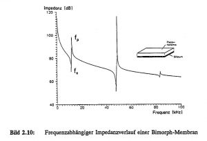
Based on the electrical equivalent circuit diagram for piezoelectric resonators [Tic 80], the series resonant frequency f_s corresponds to the electrical short-circuit condition (E=0) and the parallel resonant frequency f_p corresponds to the electrical open circuit with open electrodes (D=0). To develop suitable FE models and to verify the piezoelectric computational possibilities with ANSYS, a bimorph structure consisting of a silicon diaphragm with a piezoceramic (PZT) was selected. Precise information on material properties is available for the piezoceramic [VIB 81], so that the influence of unknown parameters could be kept to a minimal level. For the bimorph structure, the diaphragm side length was 9.2 mm, the thickness of the silicon diaphragm was 20 μm and the thickness of the piezo ceramic was 200 μm. The material behavior for the piezoceramic (VIBRIT 420) was modeled as anisotropic. The electrical excitation voltage at the full-surface electrodes was 1 V. An average value of 1000 was assumed for the mechanical vibration quality Q; the dielectric damping contributions were neglected.
Figure 2.10 shows the frequency-dependent impedance curve of the bimorph membrane calculated with FEM up to 100 kHz in logarithmic representation. Three vibration modes are clearly evident, whose electro-mechanical coupling factors decrease with increasing frequency (k_eff ≈ 29 %, 22 %, 16 %). The mechanical vibration amplitude of the fundamental mode was calculated to be around 2.5 μm. A comparison of the FE calculations with measurements shows a good agreement despite simple model approaches. The deviations in the resonance frequencies are around 1-4 %.
Figure 2.10: Frequency-dependent impedance characteristic of a bimorph diaphragm
2.3.2 Optimizing the layer thickness ratio
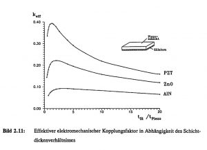
In piezoelectric excitation, knowledge of the most favorable layer thickness ratio for the highest possible electromechanical coupling is of great interest. Various bimorph models were used to investigate the influence of the layer thickness ratio of the piezo layer t_Piezo to the silicon membrane t_Si and the effect of different piezoelectric materials. Figure 2.11 shows the effective electromechanical coupling factor for AlN, ZnO and PZT ceramics as a function of the piezoelectric layer thickness for a 20 μm thick silicon diaphragm. It can be clearly seen that the different materials have different optimum layer thicknesses. For AlN, ZnO and PZT, the maximum coupling factors of 10 %, 25 % and 39 % are achieved for layer thicknesses of around 5-6 μm, 9 ± 1 μm and 15 ± 2 μm, respectively, and are therefore within the feasible range for thin-film technology. A comparison with experimental values and a detailed discussion of the influence of layer stress on zinc oxide is given in Chapter 4.
Figure 2.11: Effective electromechanical coupling factor as a function of the layer thickness ratio
2.3.3 Increased mode selectivity through electrode patterning
The excitation of resonant silicon structures to flexural vibrations is achieved by sputtered ZnO thin films, which generate expansions and contractions on the device surface as a result of the piezoelectric effect. In order to achieve the highest possible mode selectivity, it is important to know the exact stress curve on the device surface and to ensure through suitable electrode design that only expansion is generated in the area of tensile stresses and only contraction in the area of compressive stresses. The zero crossing of the lateral stress curve (i.e. the transition from tensile to compressive stress ranges) on the surface of the resonator is to be regarded as the design parameter for the electrode design.
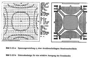
Based on a silicon diaphragm, various FE models were investigated, taking into account the influence of different diaphragm thicknesses, variable pressurization, clamping due to the etch-limiting (111) planes and non-linear effects due to stress stiffening of the diaphragm. The FE calculations result in a value of approximately 17 % of the diaphragm side length for the zero crossing of the lateral stress curve. For bending beams clamped on both sides, the zero crossing is slightly less than 25 % of the beam length. No electrodes should be placed in these areas. Figure 2.12 a shows the stress distribution σ_x on a membrane surface pressurized from below. Compressive stresses form in the edge area and tensile stresses in the center of the membrane. An electrode design for selective excitation of the fundamental mode derived directly from the surface stress distribution is shown in Figure 2.12 b.
Figure 2.12 a: Voltage distribution σ_x of a pressurized diaphragm surface
Figure 2.12 b: Electrode design for selective excitation of the fundamental mode
The mode selectivity of the fundamental mode was significantly increased and the resonance amplitude was doubled with the same activation by structuring the electrodes and activating the edge and central electrodes in antiphase. This allows the sensor to be operated in the small signal range and dynamic non-linearities caused by large oscillation amplitudes can be avoided.
2.3.4 Comparison of calculations with measurement results
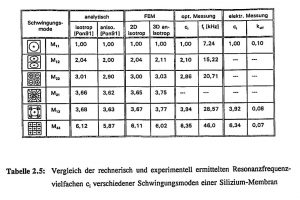
Table 2.5 compares the mathematically and experimentally determined resonance frequency multiples c_i of the vibration modes of the pressure sensor membrane. The analytically determined frequency multiples for isotropic and anisotropic material behavior are taken from the literature [Pon 91] and are based on plates with ideal clamping. For comparison, both 2D shell models with isotropic material behavior and 3D solid models with anisotropic material behavior and (111) restraint were calculated using FEM. The frequency multiples of the low vibration modes correlate well with the analytical results, while the deviation increases towards higher vibration modes.
Compared to the analytical and numerical calculations, the measured resonant frequency of the fundamental mode of a ZnO-coated silicon diaphragm is about 2 kHz lower. From this, the technologically induced internal compressive stress in the ZnO layer was estimated to be σ ≈ -15 MPa according to equation (5). For the electrical measurements, an impedance/gain phase analyzer (HP4194A) was used to measure the impedance and phase behavior of the pressure sensor membranes and the effective coupling factor k_eff was determined from the resonance frequencies f_s and f_p. Due to the mode-selective electrode arrangement, not all modes could be detected electrically, but the frequency multiples for M_13 and M_33 agree very well with the optically measured values. The deviation from the calculated values also tends to increase with higher vibration modes [Fab 92b].
Table 2.5: Comparison of the calculated and experimentally obtained resonant frequency multiples c_ij of different vibration modes of a silicon diaphragm
2.4 Summary
The requirements for the design of resonant sensors to take into account superimposed non-linear effects, anisotropic material properties and the piezo-electric interactions in multilayer systems necessitate the use of computer-aided, numerical calculation methods.
An optimization of micromechanical resonators can only be achieved by simultaneously considering the static and dynamic properties including the physical excitation principle. The investigations carried out have shown that the finite element method (FEM) is suitable for describing the behavior of micromechanical sensors. When calculating the resonance frequencies and vibration modes and the load-dependent change in resonance frequency, good agreement was achieved with the measurement results.
The ability of the ANSYS program system to perform coupled field calculations allows the behavior of piezoelectrically driven sensors to be modeled. This makes it possible to derive important specifications, such as the most favorable electrode arrangement and the optimum layer thickness ratio, for the subsequent technological process steps as early as the design phase. One of the strengths of the FE method is its ability to model complex geometries under a wide range of boundary conditions, to carry out parameter studies and to consider geometry and material influences separately.
Excerpt from the BMFT project final report, HSG-IMIT, 1993
List of references
- [Ala 92] : Alavi, M., Fabula, Th., Schumacher, A., Wagner, H.-J., Monolithic Micro-bridges in Silicon Using Laser Machining and Anisotropic Etching”, EURO-SENSORS VI, San Sebastian (1992), erscheint in Sensors and Actuators
- [Alb 82] : Albert, W.C., Vibrating Quartz Crystal Beam Accelerometer, ISA 28th. Int. Instr. Symp., Vol.28, No.1 (1982)
- [AUM 92] : ANSYS User’s Manual for Revision 5.0, Volume IV, Theory, ed. Peter Kohnke, Houston, PA, USA (1992)
- [Ble 84] : Blevins, R.D., Formulas for natural frequency and mode shapes, Krieger Publishing Company, Malabar/Florida (1984)
- [Bou 90] : Bouwstra, S., Resonating microbridges mass flow sensor, Thesis, University of Twente, Enschede, The Netherlands (1990)
- [Bri 85] : Brice, J.C., Crystals for quartz resonators, Rev. Modern Physics, Vol. 57, No. 1 (1985) 105
- [Cha 87] : Chan, H.-L., Wise, K.D., Scaling limits in batchfabricated silicon pressure sensors, IEEE Transactions on Electronic Devices, Vol. ED-34, No.4, (1987), S. 850-858
- [Fab 92a] : Fabula, Th., Schroth, A., Simulation des dynamischen Verhaltens mikromechanischer Membranen, VDI-Fachtagung für Geräte- und Mikrosystemtechnik, TU Chemnitz (1992), VDI-Bericht 960, VDI-Verlag Düsseldorf (1992)
- [Fab 92b] : Fabula, Th., Dynamische Berechnungen in der Mikromechanik – Simulation / Messung, 10. ANSYS Users’ Meeting, Arolsen, 28.-30.10.1992
- [Fra 88] : Franz, J., Piezoelektrische Sensoren auf Siliziumbasis für akustische Anwendungen, VDI-Berichte, Reihe 10: Informatik/Kommunikationstechnik, Nr. 87, VDI-Verlag Düsseldorf (1988)
- [LB 82] : Landolt-Börnstein, Zahlenwerte und Funktionen aus Naturwissenschaft und Technik, Gruppe III, Band 17a, Berlin, Springer Verlag (1982)
- [Pon 91] : Pons, P., Blasquez, G., Natural vibration frequencies of silicon diaphragms, Proceedings: Transducers of the IEEE, San Francisco (1991)
- [SASI] : Swanson Analysis Systems Inc., Houston, PA, USA
- [Sch 92] : Schroth, A., Modellierung mikromechanischer Membranen, Diplomarbeit, TU Chemnitz / HSG-IMIT (1992)
- [Tic 80] : Tichy, J., Gautschi, G., Piezoelektrische Meßtechnik, Springer-Verlag, Berlin (1980)
- [Utt 87] : Uttamachandi, D., Thornton, K.E.B., Nixon, J., Culshaw, B., Optically excited resonant diaphragm pressure sensor, Electronics Letters, Vol.23, No.4, (1987), S. 152-153
- [VIB 81] : VIBRIT – Piezokeramik von Siemens, Datenblatt, Siemens AG, Redwitz, Stand: Januar 1981
- [You 50] : Young, D., Vibration of rectangular plates by the Ritz method, Journal of applied Mechanics, Dec.,(1950) S. 448-453
GitHub Repositories
- github.com/ThomasFabula/BMFT_FASENS
- github.com/ThomasFabula/Quartz-DETF
- github.com/ThomasFabula/piezoelectric_simulation
- github.com/ThomasFabula/Modeling-of-Resonant-Silicon-Microsensors
Further informationen
German version
Testimonials
Prof. Dr.rer.nat. Stephanus Büttgenbach | Technische Universität Braunschweig


