Monolithic bridge-on-diaphragm microstructures
Abstract
Monolithic bridge-on-diaphragm (BOD) microstructures for sensor applications were fabricated by means of laser machining and anisotropic etching techniques. The pressure-frequency-characteristic was measured by acoustical excitation of the microbridge to resonant vibrations and optical detection of the resonance frequency. In the pressure range between 0.8 bar and +1.0 bar the pressure-frequency-characteristic is almost linear with a sensitivity of about 4.5 kHz/bar and with a fundamental bridge resonance frequency of 82.08 kHz. Finite element analysis was used to optimize the geometrical dimensions of the sensor structure with respect to maximum sensitivity and pressure range. With the same BOD sensor layout it is possible to realize pressure sensors for the range between 0.5 and 12 bar only by varying the thickness of the diaphragm. BOD sensors with smaller dimensions can be operated up to 100 bar with a pressure sensitivity of about 141 Hz/bar.
1. Introduction
Micromechanical sensors based on resonating elements have become important in the field of precision measurement technique because of their high sensitivity, high resolution, and semi-digital output. Resonant beams are well suited for the detection of forces, as the resonance frequency depends on the mechanical stress which is induced by an applied axial force. For the realization of pressure sensors a resonating beam connected to a diaphragm at both ends (“bridge-on-diaphragm”) is preferred. In this case the pressure sensitive element (diaphragm) and the resonator (bridge) are separated. The resonating element can therefore be encapsulated in vacuum to get higher Q-factors in order to increase the resolution.
In recent years several bridge-on-diaphragm (BOD) pressure sensors were realized. Greenwood and Satchell [1] have produced 6 µm thin resonating structures on a 6 µm thin diaphragm of highly boron doped silicon by selective and anisotropic etching techniques. Thornton et al. [2] fabricated 2 µm thin boron-doped silicon resonator structures on a 30 µm thick silicon diaphragm. Due to this fabrication technique the thickness of the resonator is limited to few microns. Furthermore, the high dopant concentration causes intrinsic stresses which determines the sensor characteristics. Buser et al. [3] used Si-Si bonding techniques to produce silicon beams with lower dopant concentrations and higher thickness on a silicon diaphragm. However, for the bonding procedure high temperatures are necessary.
Furthermore, the resonator has to be separated manually from the supporting frame, so that batch processing is not feasible. In addition, any electrical contact of the beam is difficult to realize.
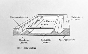
In the following we present a novel BOD microstructure for sensor applications, which has been fabricated monolithically in silicon without any use of bonding or doping techniques. The microbridge is clamped between two supporting piers which are connected directly to the diaphragm (see Fig. 1).
A pressure applied to the BOD structure leads to a deformation of the diaphragm and therefore to an axial stress in the microbridge. For sensor applications, the BOD structure can be operated with piezoresistors on the bridge surface to obtain analog output signals.
Alternatively, the microbridge can be excited to resonant vibrations either by piezo-electric thin films or electrothermally by diffused resistors, for example, and the change of the resonance frequency induced by the axial stress can be detected. Electrical interconnection between the microbridge and external bonding pads is established via the supporting piers.
2. Experimental
2.1 Fabrication process
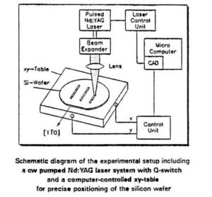
The monolithic BOD microstructure has been fabricated by combination of laser micromachining and anisotropic etching techniques. The principle of this fabrication method is based on the local destruction of {111} crystal planes by a laser beam. During the laser treatment the silicon wafer is precisely moved by a computer controlled xy-table. Following anisotropic etching in KOH solution leads to the formation of new types of microstructures [4]. In <110> oriented silicon wafers microbridges with triangular cross sections have been produced [5].
For the fabrication of the monolithic BOD microstructures three inch <110> silicon wafers with a thickness of 380 µm covered with a thermally-grown 1.5 µm SiO2 layer were used. In a standard photolithographic process the SiO2 layer was patterned to define the dimensions of the micro-bridge, the supporting piers, and the diaphragm. In a second step the crystal order of the silicon substrate was locally damaged down to a defined depth by scanning the focused beam of a Nd:YAG laser across the wafer surface. During the following anisotropic etching in KOH solution the monolithic BOD microstructure was formed.
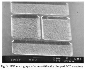
Fig. 2 shows the total view of a monolithic BOD microstructure. The dimensions of the diaphragm are 5 mm x 5 mm x 150 µm. The microbridge is approximately 2 mm long and oriented parallel to the [10] direction. Its sidewalls are consisting of {111} planes with an angle of 35ø to the (110) wafer surface resulting in a triangular cross section (width = 120 µm, thickness with approx. 37 µm). Fig. 3 shows the clamping region of the microbridge with one supporting pier (left) and the end of the bridge (right). At both bridge ends {111} planes vertical to the substrate surface were additionally left to minimize the mechanical stress in the clamping region if the sensor structure is loaded with pressure.
2.2 Measurements and results
To characterize the dynamic behaviour of the BOD structure it is excited to resonant vibrations by a piezoelectric ceramic disk and interrogated optically by a laser vibrometer (POLYTEC OFV 1102 HR). The output signal of the vibrometer is fed to a computer-controlled spectrum analyzer (Hewlett-Packard 3588A) with a personal computer data acquisition system which directly displays the frequency spectrum.
The BOD structures were mounted on a test equipment, where air pressure or vacuum can be introduced to the back side of the diaphragm while the front side including the supporting piers and the microbridge remains at atmospheric pressure. The frequency of the first fundamental bridge flexure mode was measured in dependence of the pressure difference (back side to frontside) in the range between 0.8 bar (vacuum) and +1.0 bar. Fig. 4 shows the pressure-frequency characteristic of the monolithic BOD microstructure. The fundamental resonance frequency has been determined to 82.08 kHz, and the pressure sensitivity is approximately 4.5 kHz/bar, related to the investigated pressure range. At atmospheric pressure a Q-factor of about 500 was achieved.
3. Optimization of the sensor characteristics
The following investigations were accomplished to optimize the sensor geometry with respect to the sensor characteristics, relating the pressure sensitivity and the maximal load which can be introduced to the sensor structure without break or damage. Due to the detecting principle, it is evident, that the pressure sensitivity will be enhanced if the stress in the microbridge is increased at constant pressure difference. As there are no analytical formulas available concerning the dynamic behaviour of this complex sensor geometry, finite-element (FE) analysis was used to predict the sensor characteristics and to analyse geometric modifications on the sensor performance.
3.1 Simulation of the BOD sensor structure
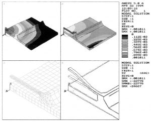
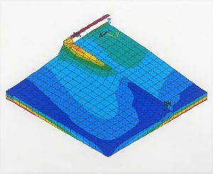
A three dimensional FE model of the sensor structure was created with I-DEAS (SDRC), and FE simulations were carried out with ANSYS using one quarter of the BOD sensor structure and considering anisotropic material properties of single crystal silicon. For these calculations a bridge length of 1.95 mm and a thickness of 42.4 µm were assumed. In Fig. 5 the geometry of the quarter model and the results of the FE calculations are presented. In the upper left window (1) the displacements uz of the sensor structure caused by a pressure difference acting on the diaphragm are shown. By applying a pressure difference of 1 bar the maximum displacement of the diaphragm is about 1 µm.
Due to the leverage principle a stress concentration occurs in the microbridge resulting in a maximum tensile stress Sigma_y of about 24.7 MPa as shown in window (2). The finite element mesh was refined in the bridge and in the clamping region as shown in window (3) to get a better stress resolution. Due to the complex geometry the BOD structure is able to vibrate in several different flexure modes. For the following calculations only the first fundamental flexure mode of the bridge and the first antisymmetric coupled mode of the bridge and the diaphragm were considered (4).
3.2 Variation of the diaphragm thickness
As a strong influence on the pressure sensitivity is expected, the diaphragm thickness was varied in the range between 50 and 300 µm while the remaining geometrical dimensions were kept constant. The corresponding resonance frequencies of the diaphragm (f_diaphragm) and the bridge (f_bridge) were calculated.
While the frequency of the first fundamental bridge flexure mode is nearly independent of the diaphragm thickness, the frequency of the diaphragm is approximately proportional to its thickness as shown in Fig. 6. At a thickness of about 130 µm there is a cross-over of the resonance frequencies. This geometrical constellation should be avoided, because the vibration energy of the bridge will be transferred into the diaphragm due to mode coupling leading to a reduction of the Q-factor. Additionally, the unimodality of the BOD sensor structure is drastically decreased.
The resonance frequencies of the microbridges were calculated in dependence of the pressure difference in the region between 0 and 1 bar for different diaphragm thicknesses. The frequency-pressure-characteristics for the first fundamental bridge flexure mode is shown in Fig. 7. As expected, the pressure sensitivity decreases with increasing diaphragm thickness. The pressure difference p_max, where the stress Sigma_max in the bridge amounts to a quarter of the break stress of single crystal silicon, had not been exceeded. For diaphragm thicknesses below 130 µm the pressure range is reduced, because the stiffnesses of the supporting piers and the diaphragm become comparable resulting in a weakening of the levering mechanism, accompanied with a decrease of the resonance frequency. With this BOD sensor geometry it is possible to realize pressure sensors in the region between 0.5 and 12 bar with identical layout only by adapting the diaphragm thickness.
The fundamental bridge resonance frequency has been calculated to 95.4 kHz which differs from the experimental value (82.1 kHz). This difference is caused by the fact, that for the simulation an ideal triangular bridge with a thickness of 42.4 µm and with a length of 1.95 mm has been assumed. In contrast, the fabricated bridge is (1.99 +/- 0.04) mm long. Additionally, its thickness is reduced to (37 +/- 5) µm, because the convex edge at the bottom of the bridge has been attacked by the etchant.
3.3 Variation of the diaphragm side length
By reducing the diaphragm side length higher pressures can be detected. FE calculations were carried out for a 2 mm x 2 mm x 300 µm diaphragm in combination with a 1 mm x 120 µm x 42.4 µm microbridge. The fundamental resonance frequency has been calculated to 386 kHz, and the pressure sensitivity is about 141 Hz/bar in the range between 0 and 100 bar. At the maximum pressure difference p_max = 100 bar a tensile stress of Sigma_max approx. 60 MPa will occur in the microbridge.
4. Conclusions
Monolithic bridge-on-diaphragm microstructures for sensor applications were fabricated by means of laser machining and anisotropic etching techniques. The fabrication procedure of the sensor structure is reproducible and suited for batch processing. As the excellent mechanical properties of single crystal silicon are preserved, sensors based on this structure have high sensitivity combined with high linearity. Furthermore, extremely high Q-factors can be achieved by vacuum encapsulation of the bridge resonator. By variation of the geometrical dimensions pressure sensors based on BOD structures can be fabricated for a wide pressure range.
5. References
- J. C. Greenwood, D. W. Satchell, Miniature silicon resonant pressure sensor, IEE Proceedings, Vol. 135, No. 5 (1988) 369 372.
- K. E. B. Thornton, D. Uttamchandani, B. Culshaw, A sensitive optically excited resonator pressure sensor, Sensors and Actuators A, 24 (1990) 15 19.
- R. A. Buser, L. Schultheis, N. F. de Rooij, Silicon pressure sensor based on a resonating element, Sensors and Actuators A, 25 27 (1991) 717 722.
- M. Alavi, S. Büttgenbach, A. Schumacher, H.-J. Wagner, New microstructures in silicon using laser machining and anisotropic etching, Proc. Micro System Technologies ’91, Berlin, Oct. 29 Nov. 1, 1991, pp. 322 324.
- M. Alavi, Th. Fabula, A. Schumacher, H.-J. Wagner, Monolithic microbridges in silicon using laser machining and anisotropic etching, Sensors and Actuators A, 37 38 (1993) 661 665.
About this article
- Authors: Wagner, H.J., Schumacher, A., Alavi, M. et al.
- Title: Monolithic bridge-on-diaphragm structure for pressure sensor applications
- Received: 13 April 1995
- Accepted: 04 May 1995
- Issue Date: September 1995
- DOI: https://doi.org/10.1007/BF01371494
Keywords
Operating Procedure, Resonance Frequency, Geometrical Dimension, Pressure Sensor, Pressure Range


